
Description :-
As you all know that Gesture Technology becomes very popular in very short time period.
So we implement here a very small application of Gesture Technology A gesture control robot.
here we make circuit on a hand glove using LDR's and LED's on our four fingers. When we turn our fingers after wearing the glove the robot moves forward, backward, left and right. So ultimately you can control your robot on your fingers.
We used here LDR as a light sensor. When light of the LED falls on LDR the resistance LDR is very high and it does not give any output. Now when we turn our finger the light of LED do fall on LDR and resistance of LDR becomes very low and it gives output.
LDR gives the analog signal so we have to convert it in Digital signal. See here.... .ANALOG TO DIGITAL CONVERTERS
We uses LM324 IC for ADC.
LM324 ANALOG TO DIGITAL CONVERTER :-
 we connects the gesture inputs to pin no. 2,6,9,13. And variable resistors at pin no. 3,5,10,12.
For this project we makes two Circuits a transmitter and a receiver. Transmitter is connected with the hand glove circuit and receiver is made on robot.
 RF module (radio frequency) :-
For making the robot wireless we use a RF module which consist a transmitter or a receiver. RF module transmits encoded signal so we have to use a Encoder - Decoder pair for encoding the signal at transmitter and decoding the signal at receiver.
This RF module works on 434MHz frequency.
Encoder :-
We use HT12E IC for encoding the signal. This is a 4 bit encoder which encodes the 4 bits into a singal bit and transmit it via RF transmitter.
 A0-A7 :-
pin no. 1 - 8 is the address line which is used for the safety purpose. You can leave blank these pins. These pins are initially high (5v) for using them lets have a example :-
Let If you ground the pins 1,2,3,4 in encoder then its address becomes 11110000 so this encoder transmit the signal to the address 11110000 so for decoding this signal decoder address must have the same address as in encoder that is 11110000. so you have ground the pin 1,2,3,4 at decoder.
AD0-AD3 :-
These are the address and data lines but we use them only for data. These are 4 input pins for 4 bit binary data for encoding.
TE :-
Transmit Enable. These should be always low(grounded) for transmission of data.
OSC1-OSC2 :-
We connect resistance of 1.1M OHM for proper oscillation.
Output :-
This is the pin for encoded data output which is further connected to the RF transmitter data pin.
DECODER :-
We use HT12D IC for decoding the signal. This is a 4 bit decoder which decodes the singal bit into 4 bits and it receive the single bit via RF receiver.


 This IC is used to drive the motors according to the signal from microcontroller.
Gesture Hand Glove Circuit Diagram :-

Transmitter Circuit Diagram :-

Receiver Circuit Diagram :-

download and zoom in the photo so you can clearly all the connections.
Pink lines - 12 volt
Red lines - 5 volts
Black lines - ground
Blue lines - data
Process to make Hand Glove Circuit :-
 First buy a soft transparent 5mm diameter tube. Cut the tube in 4 sections according to your fingers length. Now fit a LED at one side and LDR at another side. do it for all fingers see photos...

Now take a genral purpose PCB and and sold the resistors there of 330 ohm and 10k ohm and make the circuit according the circuit diagram. Leave 6 male connectors. 4 for outputs and 2 for 5v ans ground. see photo...

Now paste this circuit on a hand glove on fingers with black tap. see photo...
Now make the circuits of transmitter and receiver according to circuit diagrams.
Setting the variable resistors :-
We mount four variable resistors on transmitter. We have to set the range of resistors for better sensitivity. Follow the steps :-
1N4007 diode - 1
330 0HM RESISTANCE - 10
10K OHM RESISTANCE - 8
10K OHM VARIABLE RESISTANCE - 4
33PF CAPACITOR - 2
10UF CAPACITOR - 1
100UF CAPACITOR - 2 (ON MOTORS FOR CONTINUITY)
1000UF CAPACITOR - 2
11.0592 MHZ CRYSTAL OSCILLATOR - 1
RED LED - 2
GREEN LED - 1
12 volt battery upto 1.5 amp. -1
P89V51RD2 MICROCONTROLLER - 1
PUSH BUTTON - 1
L293D IC - 1
LM324 IC - 1
HT12E IC - 1
HT12D IC - 1
RF TRANSRECEIVER MODULE - 1
100 RPM 12V DC MOTORS - 2
7805 IC - 1
HAND GLOVE RIGHT HAND - 1
SOFT TRANSPARENT TUBE OF 5mm DIAMETER - 1 meter
BLACK TAP - 1 ROLL
GENRAL PURPOSE PCB - 1
MALE AND FEMALE CONNECTORS LINES
CONNECTING WIRES.
Enjoy the robot on your fingers.
As you all know that Gesture Technology becomes very popular in very short time period.
So we implement here a very small application of Gesture Technology A gesture control robot.
here we make circuit on a hand glove using LDR's and LED's on our four fingers. When we turn our fingers after wearing the glove the robot moves forward, backward, left and right. So ultimately you can control your robot on your fingers.
We used here LDR as a light sensor. When light of the LED falls on LDR the resistance LDR is very high and it does not give any output. Now when we turn our finger the light of LED do fall on LDR and resistance of LDR becomes very low and it gives output.
LDR gives the analog signal so we have to convert it in Digital signal. See here.... .ANALOG TO DIGITAL CONVERTERS
We uses LM324 IC for ADC.
LM324 ANALOG TO DIGITAL CONVERTER :-
we connects the gesture inputs to pin no. 2,6,9,13. And variable resistors at pin no. 3,5,10,12.For this project we makes two Circuits a transmitter and a receiver. Transmitter is connected with the hand glove circuit and receiver is made on robot.

For making the robot wireless we use a RF module which consist a transmitter or a receiver. RF module transmits encoded signal so we have to use a Encoder - Decoder pair for encoding the signal at transmitter and decoding the signal at receiver.
Encoder :-
We use HT12E IC for encoding the signal. This is a 4 bit encoder which encodes the 4 bits into a singal bit and transmit it via RF transmitter.
pin no. 1 - 8 is the address line which is used for the safety purpose. You can leave blank these pins. These pins are initially high (5v) for using them lets have a example :-
Let If you ground the pins 1,2,3,4 in encoder then its address becomes 11110000 so this encoder transmit the signal to the address 11110000 so for decoding this signal decoder address must have the same address as in encoder that is 11110000. so you have ground the pin 1,2,3,4 at decoder.
AD0-AD3 :-
These are the address and data lines but we use them only for data. These are 4 input pins for 4 bit binary data for encoding.
TE :-
Transmit Enable. These should be always low(grounded) for transmission of data.
OSC1-OSC2 :-
We connect resistance of 1.1M OHM for proper oscillation.
Output :-
This is the pin for encoded data output which is further connected to the RF transmitter data pin.
DECODER :-
We use HT12D IC for decoding the signal. This is a 4 bit decoder which decodes the singal bit into 4 bits and it receive the single bit via RF receiver.

- Address line A0-A7 must have the same configuration as in encoder. Otherwise it will not work.
- D0-D3 are data output.
- Input pin is the single bit input from RF receiver.
- We connect resistance of 51K ohm to osc1 and osc2 for proper oscillation.
- VT pin is the indicator that data is received for receiver. so we connect here a Led with 330 ohm resistance.
8051 :-
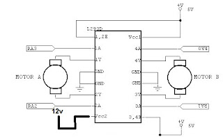
L293D(Motor Driver) :-
 This IC is used to drive the motors according to the signal from microcontroller.
- We use L293d or other motor drivers IC's for driving the motors because DC motors gives Back EMF in rotation. So from preventing the circuit from this back emf we use motor drivers.
Gesture Hand Glove Circuit Diagram :-

made this circuit on the hand glove (process is goven below)
outputs are connected to the inputs at lm324 in transmitter.
Transmitter Circuit Diagram :-
Receiver Circuit Diagram :-

Pink lines - 12 volt
Red lines - 5 volts
Black lines - ground
Blue lines - data
Process to make Hand Glove Circuit :-
 First buy a soft transparent 5mm diameter tube. Cut the tube in 4 sections according to your fingers length. Now fit a LED at one side and LDR at another side. do it for all fingers see photos...
Now take a genral purpose PCB and and sold the resistors there of 330 ohm and 10k ohm and make the circuit according the circuit diagram. Leave 6 male connectors. 4 for outputs and 2 for 5v ans ground. see photo...

Now paste this circuit on a hand glove on fingers with black tap. see photo...
Now make the circuits of transmitter and receiver according to circuit diagrams.
Setting the variable resistors :-
We mount four variable resistors on transmitter. We have to set the range of resistors for better sensitivity. Follow the steps :-
- Now check the output from hand glove from any finger when finger not turned with help of multimeter.
- Let the output is 3 volts when finger not turned.
- Now turned that finger and check the output let it will be 1 volt.
- Then set the variable resistor of that connection in LM324 between 3 volt and 1 volt. Let we set it on 1 volt.
- Repeat the above steps for all the fingers and resistors.
- Now on LM324 at positive input 1.5 volt is given ant negative input 3 volt is coming from glove circuit so the ouput will be initially high.
- Now turn the finger and at negative input the voltage becomes 1 volt which is less than 1.5 volt on positive input. So output becomes low.
- This change in output is now encoded by the encoder and decoded by the decoder then processed from mocrocontroller and drives the motors.
Components Required :-
330 0HM RESISTANCE - 10
10K OHM RESISTANCE - 8
10K OHM VARIABLE RESISTANCE - 4
33PF CAPACITOR - 2
10UF CAPACITOR - 1
100UF CAPACITOR - 2 (ON MOTORS FOR CONTINUITY)
1000UF CAPACITOR - 2
11.0592 MHZ CRYSTAL OSCILLATOR - 1
RED LED - 2
GREEN LED - 1
12 volt battery upto 1.5 amp. -1
P89V51RD2 MICROCONTROLLER - 1
PUSH BUTTON - 1
L293D IC - 1
LM324 IC - 1
HT12E IC - 1
HT12D IC - 1
RF TRANSRECEIVER MODULE - 1
100 RPM 12V DC MOTORS - 2
7805 IC - 1
HAND GLOVE RIGHT HAND - 1
SOFT TRANSPARENT TUBE OF 5mm DIAMETER - 1 meter
BLACK TAP - 1 ROLL
GENRAL PURPOSE PCB - 1
MALE AND FEMALE CONNECTORS LINES
CONNECTING WIRES.
Code for receiver microcontroller :-
----------------------------------------------------------------------------------------------------------------------------------
#include<reg51.h>
void main()
{
P1=0x0f;
P2=0x00;
while(1)
{
if(P1==0x07)
{
P2=0x0a;
}
else if(P1==0x0b)
{
P2=0x02;
}
else if(P1==0x0d)
{
P2=0x05;
}
else if(P1==0x0e)
{
P2=0x04;
}
else
{
P2=0x00;
}
}
}
----------------------------------------------------------------------------------------------------------------------------------
You can change the code according to your simplicity. Its very simple.
Pictures :-


Enjoy the robot on your fingers.
IF YOU HAVE ANY QUERY THAN CONTACT US OR GIVE YOUR QUERY IN THE QUERY OPTION.
15 comments:
Can you please share the video of this project?
What was the range?
sorry i did not make any video of this project bcoz i didnot have any video camera at that time. Now this project is submitted in college in working condition. make this project this will definatly work.
range of this project is about 10m if you use telescopic antennas on both sides then range can be increased to 50-60m.
the idea is nice but why encoder decoder ic,,, directly we can connect rf modules to the controller..... with 4800 baud rate...
thanks for suggestion. we apply it in our next project.
Hi friends,
This is kiran,
Shall i implement this as my main project in M.tech in embedded system with some improvements.
Is it good to do this project ?
Please reply me
Hi friends,
This is kiran,
Shall i implement this as my main project in M.tech in embedded system with some improvements.
Is it good to do this project ?
Please reply me
Hi friends,
This is kiran,
Shall i implement this as my main project in M.tech in embedded system with some improvements.
Is it good to do this project ?
Please reply me
will u please help me regarding to the schematics of this project.
it wiil be usefull in my BE project. please mai me the details.
my Email- biyani.suraj7@gmail.com
Every step already mentioned clearly.
can you tell me how we can control it. or we have to move our hand parallel to the receiver ckt in order to move it.
No you just have to band your fingure.
SIR CAN YOU PLEASE SEND ME THE PCB LAYOUT OF THE 3 CIRCUITS
TRANSMITTER,RECEIVER AND GESTURE HAND GLOVE TO MY EMAIL ID
kashish884singh@gmail.com
sir can you please send the pcb layout of the transmitter,receiver and hand glove circuit to my mail id kashish884singh@gmail.com
it would be a great help for our be project.
good projects
thanks for sharing.
Post a Comment